


Why does a tube amp always need to be connected to a cab?
Brian Rois | Aug 14, 2018 | Comments 0

Why does a tube amp always need to be connected to a cab?
To answer this question, we are going to have to really go deep into how tube power amps work.
 Ignoring the phase splitter to keep things simple, a tube power amplifier consists of two basic parts: the power tubes and the output transformer. The cab then connects to the output transformer through the output jack.
When dealing with power in electronics, you transfer the maximum amount of power to the load (our speakers, in this case) when the output impedance equals the load impedance. Our guitar cabs are usually in the 4-16 ohm range, so ideally we need to drive them with a matching 4-16 ohm source impedance.
To get the maximum power from our output tubes, they too need a load that matches their output impedance and this is much, much higher than the 4-16 ohms of our guitar cabinets. If we tried to load the output tubes directly with a guitar cab, we’d experience very little output.
Enter the output transformer (OT).
The output transformer solves this problem by being able to ‘transform’ impedances. So the tubes will see the high impedance load on the OT primary they want to see, and the speaker will be driven by a low impedance output on the OT secondary like it likes. Everyone is happy.
But this (clearly) is an over-simplification. Because the OT is a passive device that depends on the ratio of turns of wire on the primary and secondary windings, the actual impedance the tubes see is the ‘reflected’ impedance of the speaker.
For instance, let’s say we have a super sweet (but completely fictitious) OT with a 4k ohm primary impedance and an 8 ohm secondary. If we connect an 8 ohm speaker to the 8 ohm secondary and measure the primary, then we’ll get 4k ohm. The reflected primary impedance will be the impedance ratio times the load.
But if we put a 16 ohm speaker on the secondary, measuring the primary will give us a different result. In this case 8k ohm. The primary is a reflection of what is on the secondary.
(I promise I’m going somewhere with this.)
So, if we don’t have a cab connected at all, the load on the secondary is basically infinity freaking ohms. This means the tubes see infinity freaking ohms too.
Technically, it’s really infinity x 500 (our impedance ratio), but who’s counting?
To understand why this is bad, we need to look at what this means to the tubes.
![]()
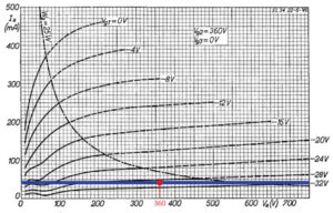
Above is a graph is called the ‘static anode characteristics’ or ‘average plate characteristics’ and is from an old Phillips EL34 data sheet. This graph plots the anode voltage (bottom) vs anode current (side). The parallel curved lines are the grid voltages, and the single curved line coming down from the top represents the tube’s maximum power dissipation.
In the graph’s blank state, the static anode characteristics aren’t very useful. The key pieces of information we need are the power supply voltage and the load.
In a standard class A/B push-pull power amp, there are actually two loads seen by the tubes: The primary impedance divided by two and four. Using our (still) fictitious OT from before, the tubes would see 2k ohm and 1k ohm. The reasons for this are well beyond the scope of this article, just take my word for it… for now.
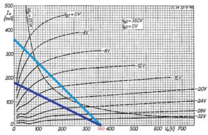
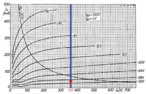
Let’s assume our power supply voltage is 360V, we can now use Ohm’s law to draw the load lines, shown in blue above. When we finally bias the amp, the 2k ohm line (Dark Blue) moves up to on the graph to bisect our idle current where the anode voltage equals our B+ (Red Dot). This is shown on the graph below.

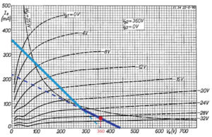
Now, we can see what the voltage across the tube and the current flowing through it will be for any given grid/input voltage. For instance, at idle (no signal), the voltage at the anode would be 360V and the anode current would be around 42mA. If a positive going signal voltage showed up on the tube’s grid, the red dot would slide up the solid lines. Let’s say we peak at -4V, the red dot would be at the point on the line where Va is 65V and the anode current is around 295mA.
Notice something interesting though. If the grid voltage gets really negative, say -36V (not plotted), we see there’s actually more voltage across the tube than our B+ voltage, which is supposed to be the maximum voltage inside the amp. This “extra” voltage is due to the inductive flyback of the output transformer.
If we disconnect the cab, we know the load is then infinity ohms. If we plot this load line, we see it is a horizontal line that passes through our bias point like before. Here we see the current in the tube will be a constant 42mA or so, but any signal is going to make the plate voltage go absolutely mental.
Now notice because the load line is horizontal, there’s no place to limit where the maximum OT flyback voltage is. This is bad. This is why we need a cab.
NOTE: Technically the voltage is limited to 2 x the B+, or 720V in this case, but again, the why and theory is beyond the scope of this article.
In the old days, high voltage insulation simply wasn’t what it is today. So it’s no surprise forgetting to connect a cab took out quite a few output transformers, in this case from arcing through the winding’s insulation. Modern insulation means modern output transformers are more apt to survive a mishap like this. Still, it’s not worth the risk.
But…
There’s another scenario that can be just as bad for the amp. Some amps use shorting jacks on their speaker outputs. The presence of shorting jacks is usually given away by a “Use First” label.
A shorting jack will short the OT secondary, thus making the load zero ohms. If the load on the OT secondary is zero ohms, then the load on the primary will be… you guessed it, zero (freaking) ohms.
Again, we can plot this load line and now we have a vertical load line. The anode voltage will remain 360V, but now the current is only limited by the tube. This situation is a little better for all involved, but there’s still some danger.
If you have happen to have this amp cranked and try to play through it, we will see the operating point spend a lot of time well above the maximum plate dissipation line. The tubes will heat up fast, and if one or more of them decide life’s just too rough, you are (at best) blowing a fuse, but it’s possible you are taking out the other tubes and the transformer.
Bad day. Really bad day.
The absolute worst thing for the amp is when a speaker jack is going bad, and is making intermittent connection.
In this situation, the load is bouncing back and forth between a good load and either zero or infinity ohms. You’re getting inductive kickback when you aren’t supposed to be, your bandmates are getting annoyed because they’ve told you to get the damn amp fixed and you didn’t, and your girlfriend leaves because now you have to replace the amp instead of buying her a ring.
And that my friend, is exactly why an amp always needs to be connected to a cab.
Tiny URL for this post:

Filed Under: Featured • Commentary / Editorials
About the Author: Brian Rois is the brainiac behind Analog Amp Modeling. He is the founder and product designer at Black Widow Audio Designs and loves to talk gear with anyone. When not designing, he can be found making his world famous artisanal pizza, which is only world famous because family in England thinks “it’s OK”.